

When you park your car on a hill, you certainly hope that it will still be there when you return. A runaway vehicle is problematic—it can cause damage to the car, other property, and, most importantly, harm or even death to people.
The parking brake can keep the car in place, but it's always good to have a backup brake, just in case. Since 1965, all cars with automatic transmissions have been equipped with a parking pawl that locks the drive wheels and prevents movement. A parking pawl is a pin or lever that engages with a parking gear installed on the transmission output shaft. When the pawl moves into the gear teeth, it locks the output shaft, preventing the drive wheels from turning.
The most common way to engage the parking pawl is by using a cable that connects the gear shift to a lever on the transmission, which in turn moves the parking pawl into position. Toyota has removed the gear shift lever and created a “drive-by-wire” shifting system and a drive-by-wire parking system for its hybrid vehicles. In this article, we will explore how the drive-by-wire parking system works.
The core of the system is the transmission control ECU. Its sole purpose is to engage and disengage the parking pawl. It is not concerned with the ratio of engine speed to vehicle speed, as those are managed by the hybrid ECU. Instead, it drives the parking pawl motor, monitors its position, sends data to the hybrid ECU and power ECU, controls the parking indicator light, and receives commands from the hybrid ECU.
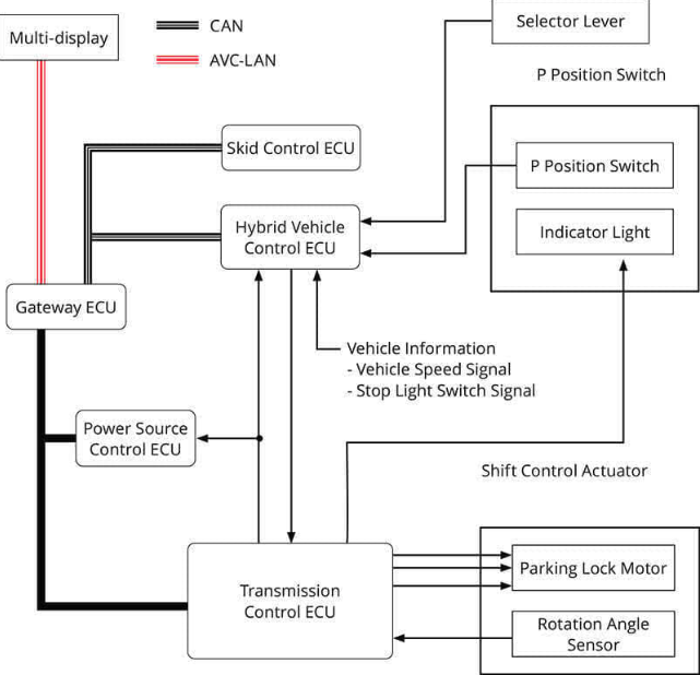
Image comes from internet.
Press the Parking Button
When the driver presses the parking button on the dashboard, the hybrid ECU receives the signal. Once it detects the vehicle speed is 0 MPH, it instructs the transmission control ECU to engage the parking pawl.
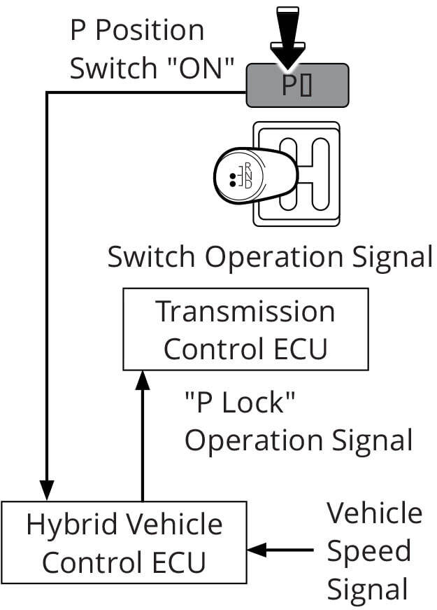
Image comes from internet.
Parking Confirmation
The transmission control ECU drives the parking pawl motor and monitors the parking pawl rotation angle sensor signal to confirm whether the vehicle is in the parked position. Once successful, it lights up the parking LED on the parking button.
Toyota hybrid vehicles are ready to park only when the vehicle is in park mode, the driver’s foot is on the brake, and the steering lock (if equipped) is unlocked. The Prius cannot be ready in neutral like other vehicles, making the drive-by-wire parking system essential.
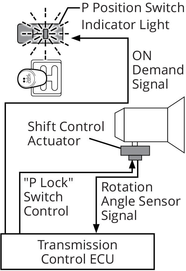
Image comes from internet.
Disengage Parking Mode
When the driver moves the gearshift to drive, reverse, or neutral, the hybrid ECU receives the input, checks if the driver’s foot is on the brake pedal, and then instructs the transmission ECU to disengage the parking pawl.
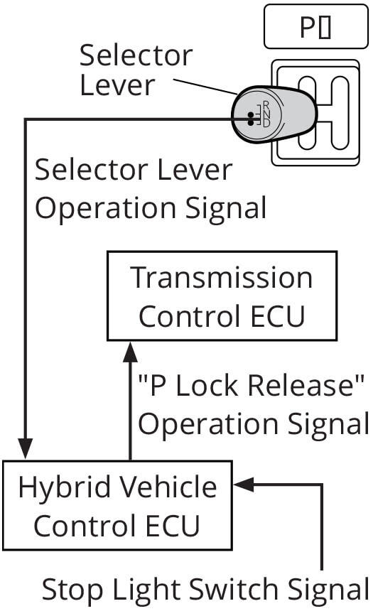
Image comes from internet.
TCU & ECU
Now, let’s put it all together and discuss how this all happens. The hybrid ECU receives input from the parking button. It sends a message to the transmission control unit (TCU) via the “PCON” line, telling it to shift to park mode. The TCU drives the actuator’s three-phase motor and monitors three Hall sensors that detect rotation. When the TCU is certain that the transmission is in park, it sends a success signal to the hybrid ECU via the PPOS line, and then the hybrid ECU lights up the parking button LED.
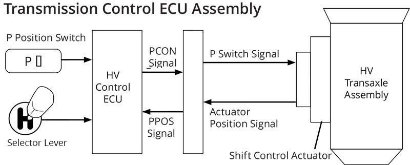
Image comes from internet.
How do the TCU and HV ECU communicate?
This is network communication, but it might not be familiar to you. Most network communication is “duplex,” meaning that messages can be sent and received on the same network connection. The TCU and HV ECU use a “simplex” network. On the PCON line, the TCU provides a 5V regulated voltage and listens when the HV ECU pulls it to ground using a transistor. Only the HV ECU can communicate on the PCON line. For the PPOS line, the HV ECU provides a 12V regulated power supply and listens to what the TCU says. The power ECU also listens to the PPOS line to determine whether the vehicle is in the parked state.
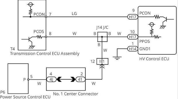
Image comes from internet.
Here, we can see what the PCON and PPOS lines look like. The service manual provides a sample waveform showing matching signals. Oscilloscope testing is much better than using an ohmmeter to check the wires. First, you can touch one end of the wire to quickly check if it’s functioning properly. Second, you can observe the wire while it’s processing the signal it was designed for. Third, you can determine if the power is coming from one unit and whether the signal control from another unit is functioning well. All of this is faster than performing a resistance test.
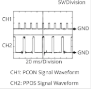
Image comes from internet.
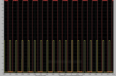
Image comes from internet.
Now let’s look at the TCU and shift actuator.
12V power is fed through the PCON relay to the center tap on the stator of the three-phase actuator motor, which is controlled by the TCU.
The TCU alternates grounding the three phases of the motor using transistors, causing the rotor to rotate.
The TCU uses Hall effect sensors mounted near the rotor to monitor rotation. The rotation sensors have three outputs: RA, RB, and RZ.
RA and RB produce three pulses per revolution, while RZ produces one pulse per revolution.
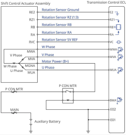
Image comes from internet.
This oscilloscope capture has four signals. Since most oscilloscopes have only four channels, it makes sense to exclude the W and V phases from the capture in favor of including all three rotation sensor signals.
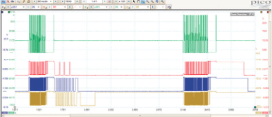
Image comes from internet.
On the top, the green trace is the U-phase signal from the TCU to the 3-phase motor. You may notice that the voltage is quite high—around 40V. This is just a 12V motor though. The high voltage peaks are just spikes from the magnetic field collapsing as power is cut to the U-phase winding.
The red, blue, and yellow traces are the rotation sensors. The red trace is the RZ signal, so there are fewer peaks, since it produces only one pulse per rotation. The blue is the RB signal and the yellow is the RA signal. Both RB and RA produce three pulses per rotation.
In this capture, the parking pawl is released, then after about 1 second, it’s re-engaged. You may notice that in the first series of pulses the motor is driven (green trace), held for a moment, and then released. When the TCU stops holding the motor, it spins on its own (red, blue, and yellow traces). This is due to a detent sucking the parking pawl into position away from the output shaft sprocket.
When the motor re-engages the parking pawl, it must drive the motor the entire way home.
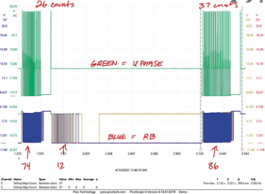
Image comes from internet.