

Compensation in wireless power transfer (WPT) refers to using additional circuit elements to counteract the reactive power in the charging system. Simple compensation topologies are S or P-type, while basic compensation topologies include SS, SP, PS, and PP types.
The topologies are categorized based on the placement of compensating elements at the primary (transmitter), secondary (receiver), or both. It’s also categorized based on the number of compensating elements used in the primary and secondary coils.
How does reactive power flow affect WPT performance?
The reactive power flow is due to inductance in the transmitting and receiving coils. It does not contribute to the actual power transfer and keeps circulating between the source and the load. This phenomenon, in turn, causes a higher flow of current, and anyone working on power electronics will know that a higher current also translates into high power loss.
When the reactive power flow is minimized with the help of a compensation topology, it naturally leads to improved power transfer efficiency and reduced energy losses. As such, the transmitting and receiving coil operates at or near resonance, an ideal condition for maximum power transfer.
Why do we need capacitors and inductors in compensation topologies? Because the inductive reactance and capacitive reactance work in tandem to cancel each other. Therefore, when a particular type of reactance is more, the opposite reactance can be used to bring the system into balance with no reactive power flow.
The compensation circuit consists of combinations of capacitors and inductors, resulting in several forms of compensation topologies: simple, basic, and hybrid.
Figure 1 shows how the three types of compensation topologies can be arrived at by adjusting the placement and number of components. The hybrid type will be covered separately as it’s outside the scope of this article.
It should be noted that “S” denotes the placement of the capacitor as a series, and “P” denotes that the capacitor is placed parallel at one end to both ends of the charging coil, depending on the topology.
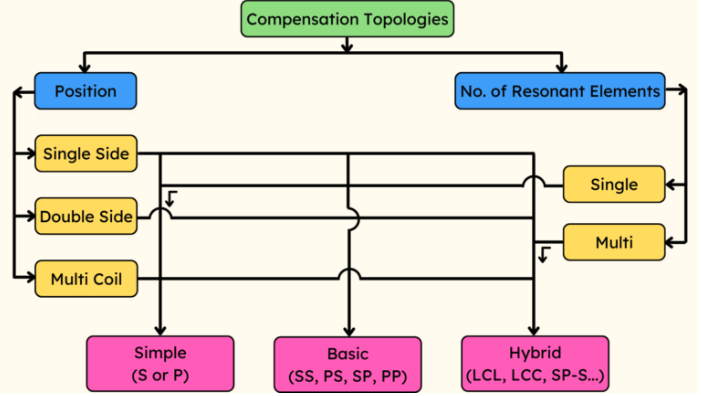
Figure 1. The different compensation topologies, which are based on the position and number of resonant elements. (Image: Rakesh Kumar, Ph.D.))
Simple (S or P) compensation topologies
The simplest compensation topology is the S or P-type, which refers to configurations where the capacitor is added in series or parallel to the system’s primary (transmitter) or secondary (receiver) side.
These topologies are designed to improve the efficiency and performance of the power transfer. This is achieved by tuning the system to operate at or near resonance.
Series compensation (S): The compensation capacitors are connected in series with the coils in this topology. Series compensation helps create a resonant circuit at the operating frequency, which is beneficial for applications that require a constant voltage. It also helps achieve a condition known as zero voltage switching (ZVS), which reduces switching losses in power electronic devices.
Parallel compensation (P): In parallel compensation, the capacitors are connected in parallel to the coils. This configuration adjusts the coil’s natural frequency to the system’s operating frequency. It is similar to series compensation but with different electrical characteristics and effects. Parallel compensation is often used where maintaining a constant current is necessary. It also tends to provide better tolerance to variations in coupling conditions between the transmitter and receiver.
Basic compensation topologies
Basic compensation topologies are the practical ones to start with for EV WPT applications. Note that each basic topology combines two alphabets, S and P. The first alphabet refers to the type of compensation in the WPT’s primary side coil, and the second alphabet refers to the type of compensation in the WPT’s secondary side coil.
• Series-Series (SS): The transmitter and receiver coils are connected in series with capacitors, as illustrated in Figure 2. This topology is beneficial for its simplicity and effectiveness in maintaining constant voltage across varying load conditions.
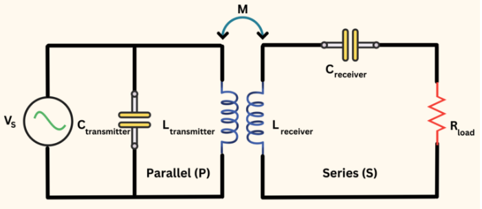
Figure 2. An SS compensation topology type. (Image: Rakesh Kumar, Ph.D.)
SS topology is known for its high efficiency, independence from the magnetic coupling coefficient, and load on the resonance frequency. It’s suitable for systems with long primary tracks.
• Series-Parallel (SP): Figure 3 shows the SP type where the transmitter coil is connected in series with a capacitor, while the receiver coil is connected in parallel with a capacitor. This topology is useful for applications that maintain a constant current output despite variations in coupling conditions or load. It’s also known for impacting the compensating network’s power factor and the input-to-output voltage transfer function. The SP compensation topology is particularly suitable for applications with varying load impedance.
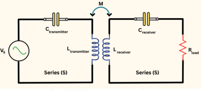
Figure 4. A PS compensation topology type. (Image: Rakesh Kumar, Ph.D.)
• Parallel-Series (PS): In this topology, the transmitter coil is connected in parallel with a capacitor, and the receiver coil is connected in series with a capacitor (Figure 4). It is suitable for scenarios where the primary goal is to enhance the voltage gain across the system.
The PS compensation topology is particularly suitable for applications with weak magnetic coupling. It offers advantages such as improved power factor, increased power transfer efficiency, and better performance in weak coupling situations.
Reposted from the WeChat official account: qicheyanjiuyuanauto