

Electric vehicle (EV) charging infrastructure consists of several individual power management components. Dc power electronics are the heart of power management, whereas charge controllers assist the dc power electronics in proper control. The role of dc and ac meters is much more than they are thought of while cooling units and charging cables are also discussed in this FAQ.
Figure 1 neatly puts all the power management components in a single picture. When we talk exclusively about power management in EV charging, it is understood that we are referring to dc fast charging applications, as in this case.
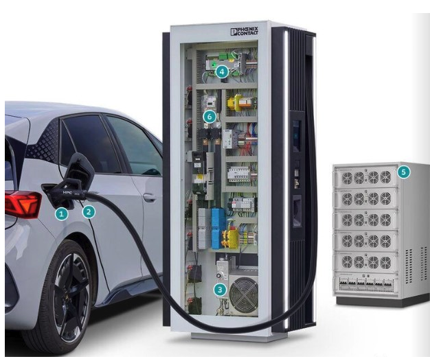
Figure 1. The main components of an EV high-power charging infrastructure: 1. Charger; 2. Charging cable; 3. Cooling unit; 4. Dc charging controllers; 5. Dc power electronics and distribution, 6. Dc energy meter. (Image: Phoenix Contact)
Below, we discuss the power management components in EV charging stations.
DC power electronics
While dc is the predominant form of power exchange over AC, several types of converters used in power electronics involve ac and dc. The types of power electronics converters in EV charging stations include:
- Dc-dc, ac-dc (rectifier)
- Dc-ac (inverter)
- Ac-ac (cyclo converter)
Figure 2 shows the various power electronics topologies within each converter type. Dc-dc converters share the majority of the topologies, as dc power is ultimately used to charge the EV battery. Among these topologies, the isolated configuration’s traditional full-bridge, flyback, and push-pull converters are well suited for high-power dc fast-charging applications.
The ac-dc converters are next on the priority list, and applications are found in Level 1 and Level 2 charging stations. Once the ac is converted to dc, a dc-dc converter finds its place again. However, low-voltage dc-dc converters, such as conventional buck, boost, and buck-boost converters or two-stage SEPIC, CUK, and Zeta converters are useful.
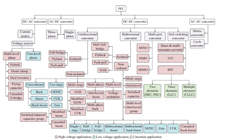
Figure 2. The classification of different power electronics topologies that can be employed in an EV charging station. (Image: IEEE)
A dc-ac converter can feed the supply back to the grid from the EV during V2G charging. Flying capacitor and cascaded H-bridge inverters have seen extensive usage for this purpose as they support high-voltage applications. The ac-ac converters are the least on the priority list, and their usage has been very limited to nil in EV charging stations.
Dc charging controllers
As seen in Figure 3, the primary purpose of the charging controller is to act as a closed-loop feedback system to coordinate the charging purpose. The way to coordinate the charging is to control the voltage and current based on the battery’s state of charge and temperature.
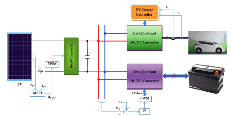
Figure 3. A block diagram of an EV charging setup highlighting the role of charge controllers. (Image: MDPI)
Dc charging controllers serve multiple purposes, including remote management, multiple connector support, grid integration, and data collection and monitoring. Software can support the charge controllers so that as demand for higher power levels increases and new charging standards evolve, the entire EV charging infrastructure can be updated via the software.
Dc and ac energy meters
Dc and ac energy meters help accurately measure and monitor energy consumption during EV charging. The purpose of the energy meters is not merely to display the meter reading but also to optimize energy allocations, as these energy meters are becoming “smart.”
Dc energy meters are integral to Level 3 charging stations, which provide direct dc power to EVs (Figure 4). The energy meters help bill and monitor power quality, detecting issues like harmonic distortion that can affect both the charging station and the grid.
Ac energy meters are commonly used in Level 1 and Level 2 charging stations, which rely on the ac power supplied by the electrical grid (Figure 4). Some advanced ac meters can log historical data, allowing for detailed analysis of energy usage patterns. This data can also help identify peak usage times and optimize charging schedules to reduce costs and improve grid stability.
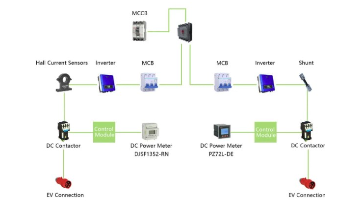

Figure 4. A line diagram of dc and ac energy meters used for EV charging. (Image: Acrel Co., Ltd)
Power cooling units and charging cables
The power cooling units and charging cables have built-in thermal management. Such thermal management indirectly helps in power management when a higher amount of power can be pumped into the EVs.
Plastic tubes offer an efficient solution for dissipating heat from high-power EV charging stations (Figure 5 (a)). Their lightweight nature, resistance to corrosion and wear, lower flow resistance, and compact design make them an ideal choice. The coolant flows through these tubes with ease, effectively removing heat from the EV charging station.
The other cooling method, as shown in Figure 5 (b), is the usage of a heatsink with the possibility of a cooling fan mounted on the heat sink. Although the heat sink consumes sufficient space, from the power electronics thermal management point of view, it’s a proven heat dissipation method.
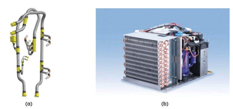
Figure 5. The power cooling units in EV charging stations, using: (a) plastic tubes; and (b) a dedicated cooling system. (Image: E-Motec.net)
Charging cables are the last point of contact in an EV charging station when considering thermal management. Figure 6 shows an example, where a liquid coolant is used on the dc charging cable to dissipate heat at the connectors. Therefore, the high power continues to flow into the EV as the temperature is kept within the permissible limit.
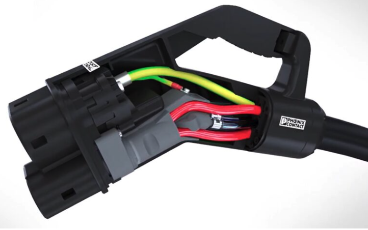
Figure 6. A cross-section of a CCS connector showing the use of liquid cooling for dc charging cables (red). (Image: Return