

Li-ion batteries can store large amounts of energy, and they can support high rates of power delivery. They are the preferred energy storage technology for EVs and large battery energy storage systems (BESS). But if not properly managed, they can also present safety hazards. That makes functional safety a critical consideration when designing large Li-ion batteries like those found in EVs and BESS.
This FAQ reviews the importance of maintaining operation in the safe operating area (SOA) of lithium batteries along with the functions of the battery management system (BMS), then briefly presents some basic concepts of functional safety defined in IEC 61508, ISO 26262, and UL 1973, looks at definitions for hazards versus risks and examples of functional safety assessments, and it considers challenges related to the use of combo boxes, multi-core processors and redundant system architectures for BMS.
The main factors that impact Li-ion safety include voltage, current, temperature, and mechanical damage. Mechanical damage is generally related to accidents or misuse of the cells. SOA is primarily a function of V, I, and T with the exact values varying based on the Li-ion chemistry being used (Figure 1). If a Li-ion cell is operated outside the SOA, secondary reactions can start leading to cell degradation and possibly dangerous conditions. At a basic level, a Li-ion battery pack includes sensors for V, I, and T that the BMS uses to keep operating within the SOA. Some packs also include gas detection and other sensors to provide an early warning of dangerous conditions arising from mechanical damage or operation outside the SOA.
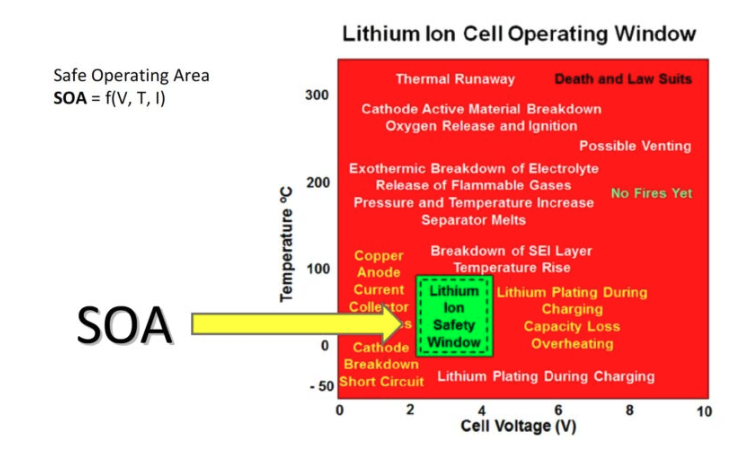
Figure 1. Understanding the SOA of a specific Li-ion chemistry is key to meeting functional safety requirements (Image: Lithium Balance A/S).
While the details vary depending on the cell chemistry, the current is the largest contributor to heat generation in Li-ion cells. High currents can also cause accelerated cell aging. Excessive voltage and overcharging are also safety concerns and can result in cell damage. If a cell is overcharged, side reactions can occur that generate gases and heat that can cause cell venting and in extreme cases, start a fire.
A well-designed BMS and a power monitoring and disconnection unit (PMDU) are central to the safe operation and long lives of Li-ion cells. Large battery packs like those in EVs and BESS are comprised of numerous modules. Every cell in each module must be monitored for cell balancing in addition to concerns with V, I, and T. Due to variations in the manufacturing process, the battery cells in the modules are not perfectly matched, and the BMS is required to support cell balancing. Imbalances between cells cause them to charge at different rates and can result in unsafe conditions in the module. The BMS monitors the charging of individual cells and compensates for imbalances.
In addition to a suite of sensors, the BMS includes several parameter estimation algorithms. Safe and reliable battery pack operation depends on the state of charge (SoC) to determine the remaining capacity in the battery, the state of health (SoH) that estimates the capacity fade experienced by the pack as it’s charged and discharged numerous times, and the state of power (SoP) that indicated the power delivery capability of the battery.
The safety goals defined in the various standards provide an expected performance level of the BMS and overall battery system. They are derived using a safety analysis based on two factors:
- Hazard Identification: A hazard is anything that may cause harm including physical injury or damage to health.
- Risk Analysis and evaluation: A risk analysis quantifies the chance that a person can be harmed by a hazard including an evaluation of how serious the harm could be.
Functional safety can be designed into a battery pack, and its efficacy is confirmed using a variety of management approaches. For example, product development teams should include a specific focus on safety management and implementation of safety specifications; quality assurance teams can perform safety assessments including confirmation reviews and process audits, and a dedicated functional safety competence center can be implemented to support technical reviews and assessments of the process and its results (Figure 2).
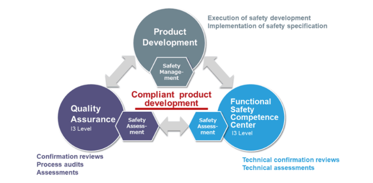
Figure 2. Designing functional safety in a battery pack requires the coordination of multiple disciplines (Image: Renesas).
The performance and cost benefits are certainly attractive, but it’s not quite that simple. Integrated systems can present challenges related to manufacturability, noise levels, thermal management, and safety. If one or more of the integrated systems are safety critical like the BMS or the drivetrain inverter, the entire combo box can be subject to difficult ASIL demands. Examples of safety-critical systems include certain dc/dc converters, the drivetrain inverter and motor, the battery charge controller, OBC, and BMS (Figure 3).
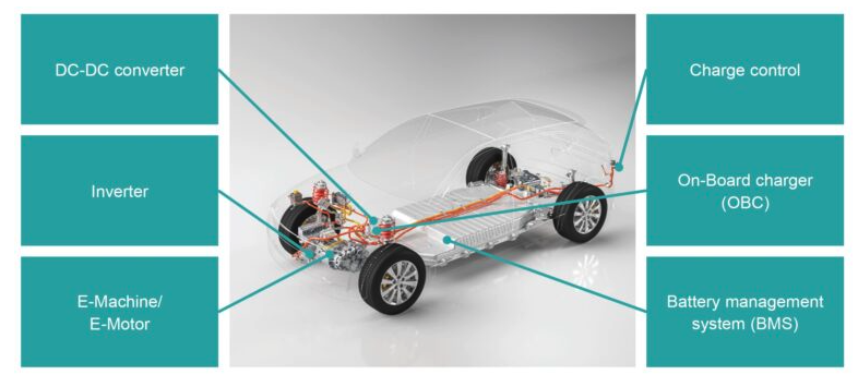
Figure 3. The use of combo boxes is growing in EV powertrain systems and increasing the challenges related to meeting ASIL requirements (Image: Siemens).
The required ASIL qualification applies to the software running the system as well as the hardware. To achieve ASIL functional safety, an MCU and an AUTOSAR (AUTomotive Open System ARchitecture) software stack with multi-core support and AUTOSAR basic software (BSW) are needed. AUTOSAR is the global standard for software enabling open E/E system architectures for intelligent mobility platforms like EVs needing high levels of dependability, particularly safety, and security.
Multi-core implementations can contribute to performance improvement by reducing the load on individual CPUs and consolidating auxiliary functions like communications on a dedicated core. In addition, different subsystems may need different approaches to ASIL compliance that can be more effectively addressed using dedicated cores.
Problems can occur if connectivity between the battery cells and the IC is lost as a result of an open or short circuit. If that happens, a hazardous event may develop. One solution is the use of bidirectional ring communication and a redundant path for battery voltage measurement that provides fault tolerance and increases pack safety by ensuring continuous monitoring. If an open or short fault occurs in one of the redundant ring communication paths, the MCU can continue communicating with the battery monitoring ICs by switching the direction of the communication to the redundant path that is continuing to operate normally with no loss of temperature or voltage information ensuring uninterrupted safety (Figure 4).
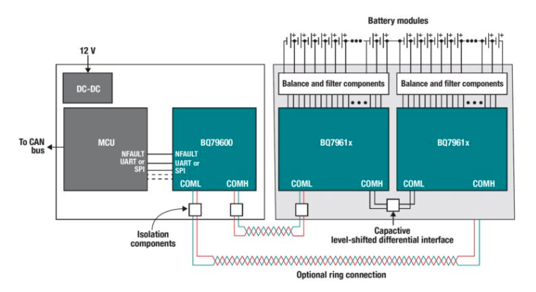
Figure 4. The use of redundant communications in a BMS can improve safety performance (Image: Texas Instruments).
Reposted from WeChat official account: qicheyanjiuyuanauto