

This article introduces dc-based architecture and discusses its advantages and disadvantages for EV charging infrastructure. A case study is also presented at the end on the effect of this architecture on the total harmonic distortion of the power grid.
What is a dc-based architecture for EV charging?
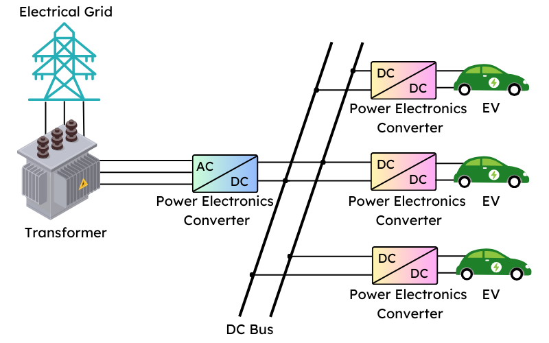
A dc-based architecture consists of a single ac-dc converter connected to a common dc bus at the output. From the common dc bus, several EV charging points are derived with the help of a dedicated dc-dc converter for each charging point.
Figure 1 illustrates the concept of the architecture where the power supply is drawn from the electrical grid through a transformer. The three charging points can be extended if the transformer can withstand the load.
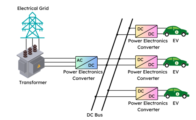
Figure 1. A dc bus-based architecture for EV charging. (Image: Rakesh Kumar, Ph.D.)
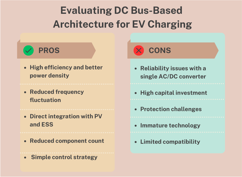
The dc-based architecture has several advantages, including the reduced conversion stages as a notable feature. However, this architecture also poses some disadvantages.
Figure 2 evaluates the pros and cons of the architecture, with a brief explanation that follows.
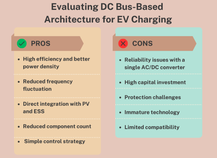
Figure 2. Evaluating dc bus-based architecture for EV charging. (Image: Rakesh Kumar, Ph.D.)
How can the dc architecture help EV charging infrastructure?
- Lower component count: Dc-based architectures generally require fewer components than ac-based systems, which include rectifiers, inverters, transformers, and other auxiliary equipment. By eliminating some of these components, dc charging systems can be more compact, cost-effective, and easier to install and maintain.
- Reduced frequency fluctuation: Dc-based architectures involve fewer conversion stages, helping reduce frequency fluctuation and exhibiting lower impedance compared to ac systems.
- High efficiency and better power density: Due to fewer conversion stages and reduced losses, dc-based charging systems exhibit higher efficiency than ac-based systems. This higher efficiency translates into better power density, meaning more power can be delivered within a given volume or footprint of the charging infrastructure.
- Direct integration with PV and energy storage system: PV panels produce dc electricity, and the energy storage system stores electricity in dc form. Using a dc architecture makes it easier to connect these components directly, resulting in higher efficiency and reduced losses associated with multiple conversions.
- Simple control strategy: Dc-based architectures often feature simpler control strategies compared to ac-based systems. With fewer conversion stages and components involved, the control algorithm can be streamlined, making it easier to implement and maintain.
Are there any associated disadvantages of this architecture?
- Reliability issues with a single ac-dc converter: Dc-based architectures rely on a single ac-dc converter for power conversion. Therefore, the stakes are high, and the converter failure can lead to a complete shutdown of the architecture.
- High capital investment: Implementing dc-based architecture often requires significant upfront investment compared to ac-based systems. This is due to the need for specialized equipment such as dc chargers, dc-dc converters, and energy storage systems.
- Protection challenges: Dc-based architectures may present challenges related to overcurrent, overvoltage, and other protection issues. Since dc systems operate at higher voltages and currents than ac systems, ensuring adequate protection measures is crucial to preventing damage to equipment and ensuring user safety.
- Immature technology: Compared to traditional ac-based charging systems, dc-based architectures are still relatively new and less mature. This could result in more significant uncertainty regarding long-term performance, reliability, and compatibility with evolving standards and regulations.
- Limited compatibility: Dc-based charging systems may have limited compatibility with existing ac-based infrastructure and vehicles. This could restrict interoperability and require retrofitting or replacing existing infrastructure to accommodate dc charging.
Figure 3 represents the voltage THD, and Figure 4 represents the current THD in percentage for the two cases under the four transformer configurations.
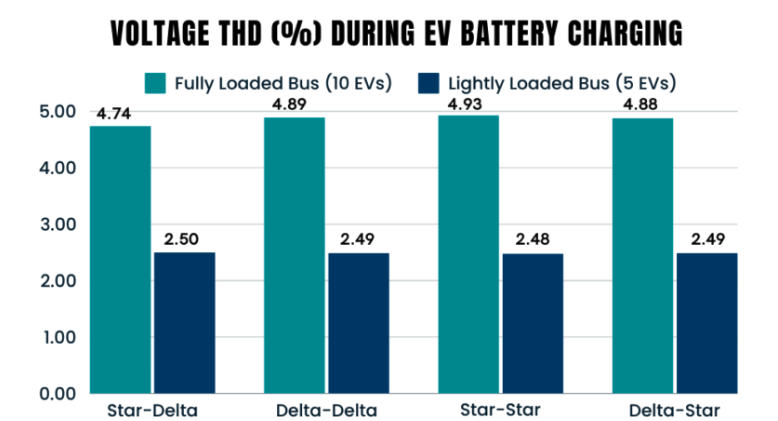
Figure 3. Voltage THD (%) during battery charging of dc bus compared for four different transformer configurations under fully loaded and lightly loaded bus conditions. (Image: Rakesh Kumar, Ph.D.)
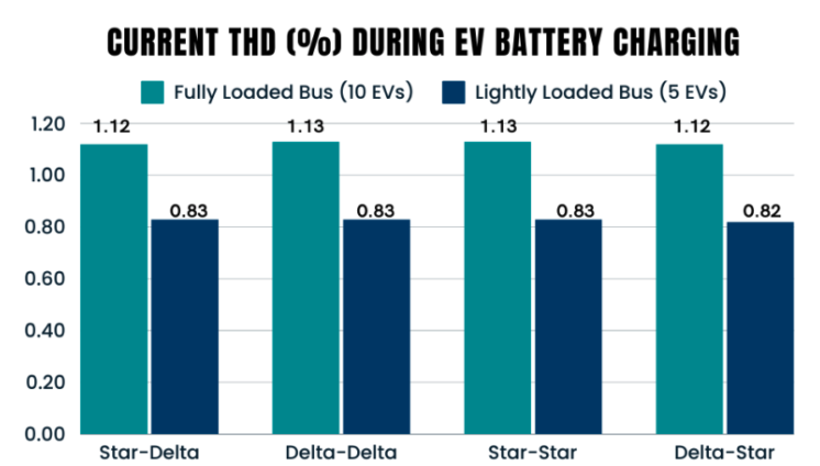
Figure 4. Current THD (%) during battery charging of dc bus compared for four different transformer configurations under fully loaded and lightly loaded bus conditions. (Image: Rakesh Kumar, Ph.D.)
Here are some observations from the two charts:
1. The voltage THD is higher than the current THD for all four configurations under both cases.
2. Barring the voltage THD under the fully loaded case, the voltage and current THDs are almost the same across the four transformer configurations.
3. Interestingly, the star-star configuration has seen the highest and lowest voltage THD for fully and lightly loaded bus conditions, respectively.
Reposted from the WeChat official account: qicheyanjiuyuanauto